
Printing principle of thermal printheads
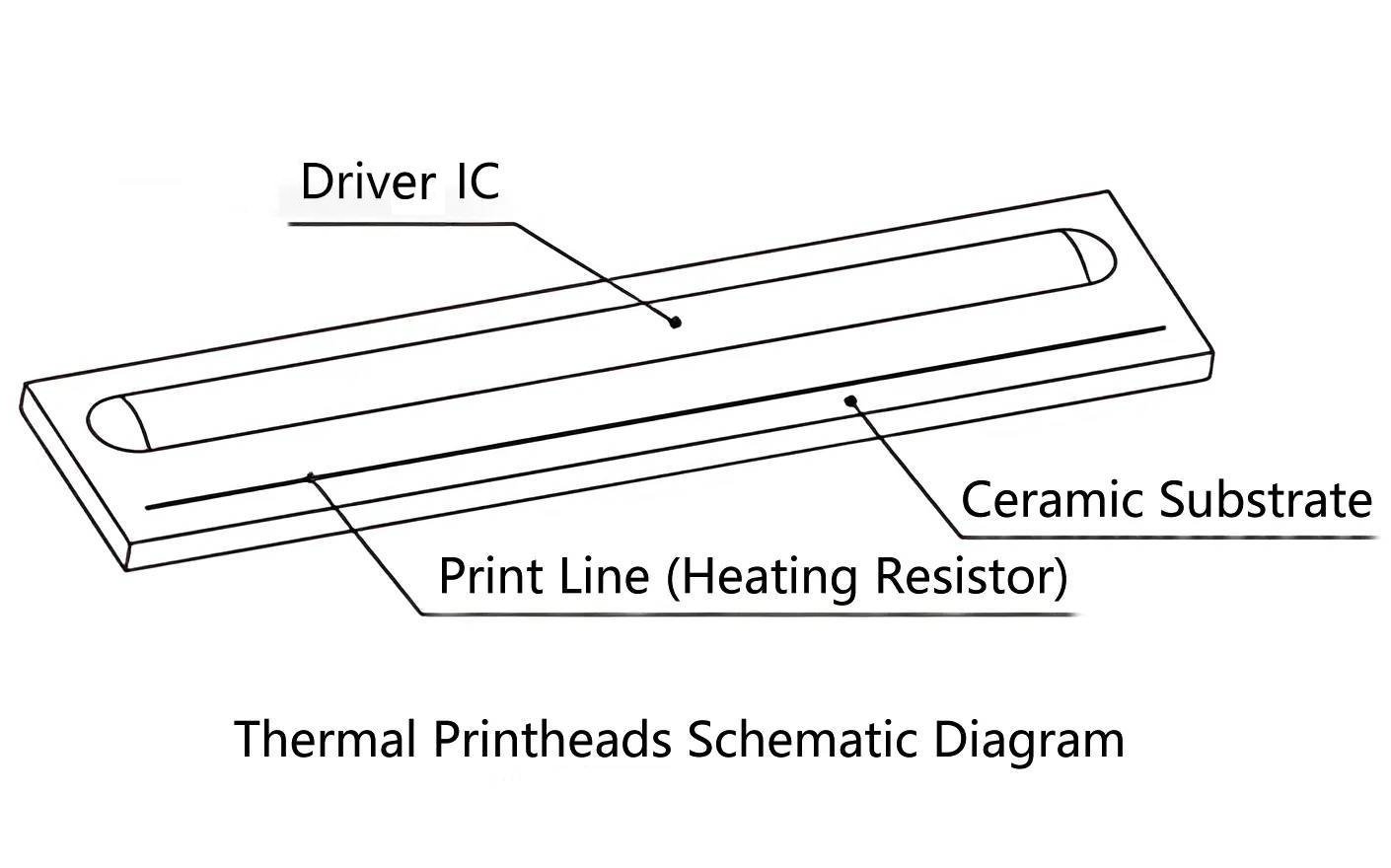
The Core of Thermal Printheads
The core of a thermal printhead (TPH) is the print line, which consists of a row of heating resistors. These resistors are theoretically identical in resistance and are arranged very densely, with a resolution ranging from 200 dpi (dots per inch) to 600 dpi. When a current flows through these heating elements, they rapidly generate high temperatures. Under a certain amount of pressure, when the coating of the printing medium comes into contact with these heating resistors, the temperature at the contact points rises in an extremely short time, causing a chemical reaction in the coating that produces visible color.
Operating Principle
The fundamental working principle of a thermal printhead is to use a driver IC to control the conduction of some or all of the heating resistors.
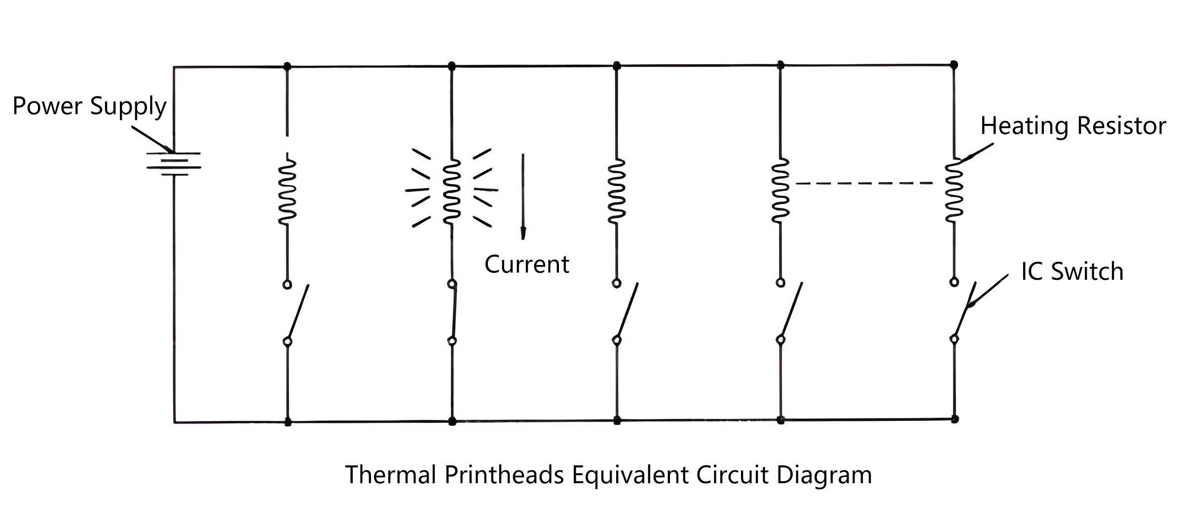
As shown in the diagram, when a current flows through the resistors, part of the energy is produced by electrical work done on the resistors, denoted as power P. Additionally, power is also consumed simply by current passing through the circuit, denoted as PL. The total power is the sum:
P₀ = P + PL
If the heating duration is represented by Ton (milliseconds), the energy used for printing can be calculated using the formula:
Printing Energy = P × Ton (Unit: mJ/dot)
Resolution of Thermal Printheads
Resolution refers to the number of heating dots per inch or per millimeter along the direction of the print line. It is expressed as dots/inch or dots/mm. The resolution is determined during the manufacturing process of the printhead using photolithography masks.
The most commonly used resolutions are 200 dpi and 300 dpi, which are sufficient to meet the requirements of most applications. Different series of printheads may support various printing widths depending on their specifications.
Example: Printing the Letter "A"
To illustrate the concept, consider printing the letter A, represented as a 16×15 pixel dot matrix:
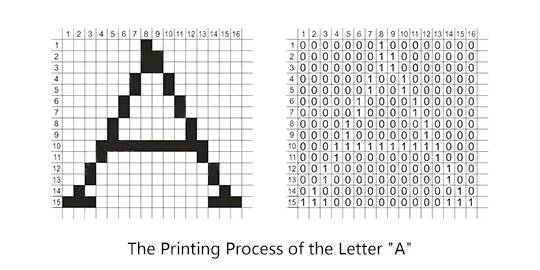
During printing:
- Each heating resistor corresponds to a pixel
- By inputting binary data (0 or 1), the driver IC controls whether each resistor is turned on or off
- 0 means the point is not printed
- 1 means the point is printed
For example:
- Row 1 input: 0000000100000000 → print at column 8 of row 1
- Row 2 input: 0000000110000000 → print at columns 8 and 9 of row 2
This continues row by row until all 15 or 16 rows are processed, resulting in the complete printed image of the letter A.